
Shower channel
Pera. Open, elegant, floor-level.
Visible drainage on an open channel body with built-in fall. Up to 160 cm, can be cut down from 32 cm, 360° rotating drain pot.
Build-up
The drain you are allowed to see.
Pera shows the water: the open channel body with its built-in fall carries it visibly to the outlet. No grate, no frame, nothing that can clog. Cleaning takes seconds.
Frame and cover in stainless steel 1.4301, waterproofing membrane fitted watertight at the factory, abP-tested.
Exploded view
Four layers, one line in the floor.
Scroll: cover, insert, channel body and siphon come apart.
The textile waterproofing membrane is fitted to the channel body at the factory — it is already in place when the bonded waterproofing is applied.
Cover and insert in stainless steel 1.4301. The outlet turns to the side, which keeps the installation height low.
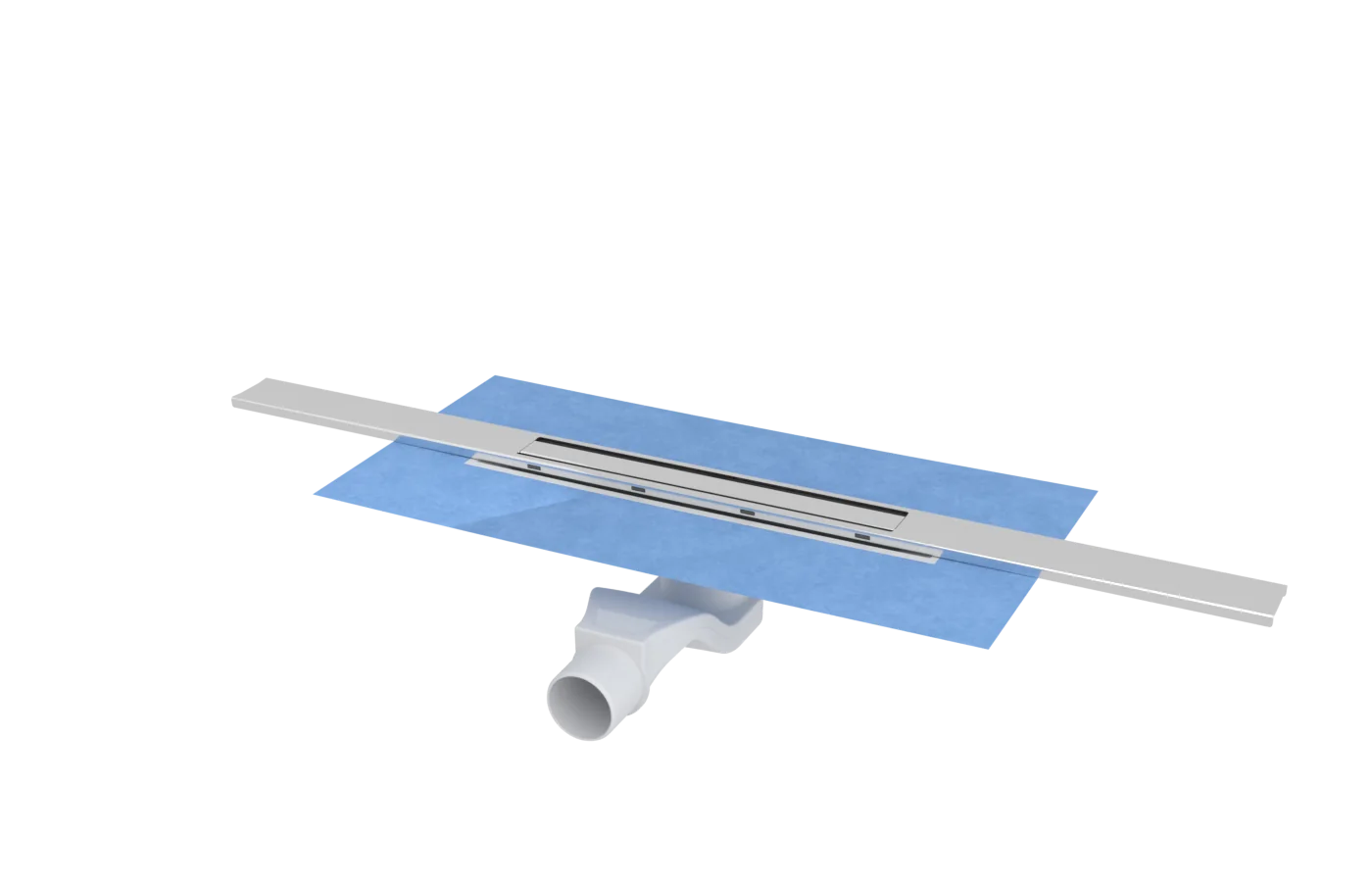
From shell to tile.
Keep scrolling: three steps, one picture.
Technical data.
| Material | Stainless steel 1.4301 / V2A (AISI 304), frame and cover |
|---|---|
| Lengths | 60 · 80 · 100 · 120 · 140 · 160 cm, can be cut from 32 cm |
| Build height | 60–100 mm, measured from the top of the sealing collar |
| Drain | 360° rotating drain pot, DN 50 outlet, integrated trap |
| Flow rate | 0.80 l/s (48 l/min) with the standard siphon, trap water height 25 mm |
| Waterproofing | Waterproofing membrane fitted at the factory, abP-tested bonded waterproofing system |
| Application | Floor-level showers in housing, hotels, spas and sports facilities; new build and renovation |
| Testing | abP, EN 1253 |
Ordering information.
12 variants.
| Item number | Size | Surface |
|---|---|---|
| LP13-H24L100E9 | 100 cm | Brushed anthracite |
| LP13-H24L100E1 | 100 cm | Brushed stainless steel |
| LP13-H24L120E9 | 120 cm | Brushed anthracite |
| LP13-H24L120E7 | 120 cm | Brushed bronze (PVD) |
| LP13-H24L120E4 | 120 cm | Brushed gold (PVD) |
| LP13-H24L120E1 | 120 cm | Brushed stainless steel |
| LP13-H24L140E1 | 140 cm | Brushed stainless steel |
| LP13-H24L160E9 | 160 cm | Brushed anthracite |
| LP13-H24L160E1 | 160 cm | Brushed stainless steel |
| LP13-H24L80E9 | 80 cm | Brushed anthracite |
| LP13-H24L80E1 | 80 cm | Brushed stainless steel |
| Made for your project — special lengths, finishes, sizesNot held in stock; lead time on request. | ||
| LP13-H24L60E1Project | 60 cm | Brushed stainless steel |
Identical for every variant: Material Stainless steel 1.4301 / V2A (AISI 304) · Outlet DN 50
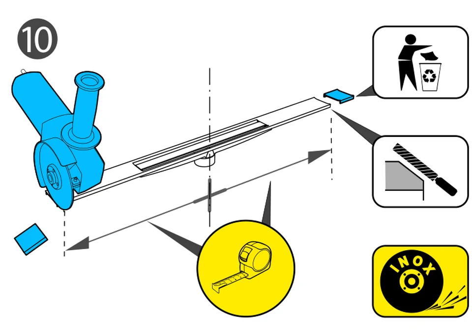
Special lengths on request. Every channel can be cut to size on site.
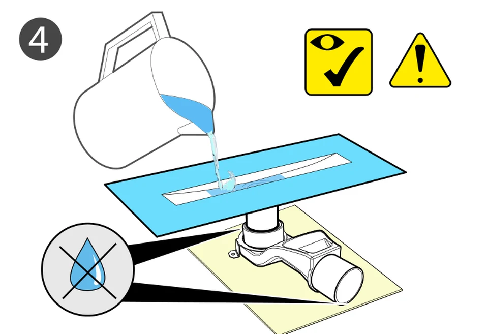
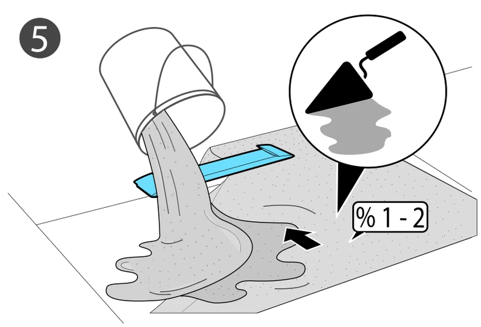
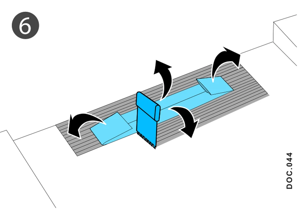
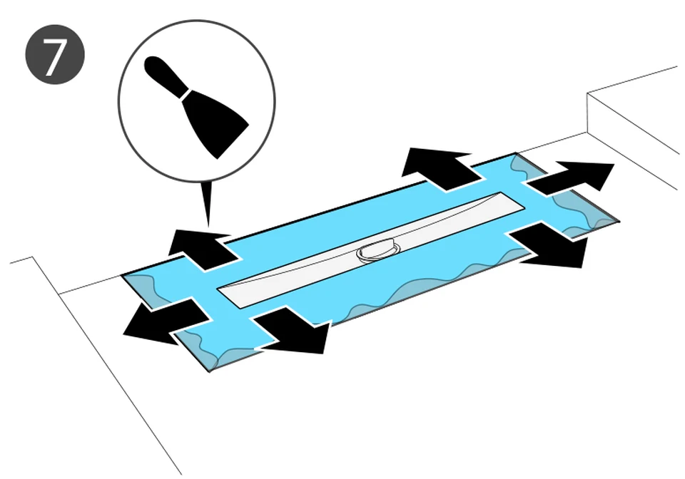
Installation in five steps.
The order follows the site: shell first, tile last.
Installation
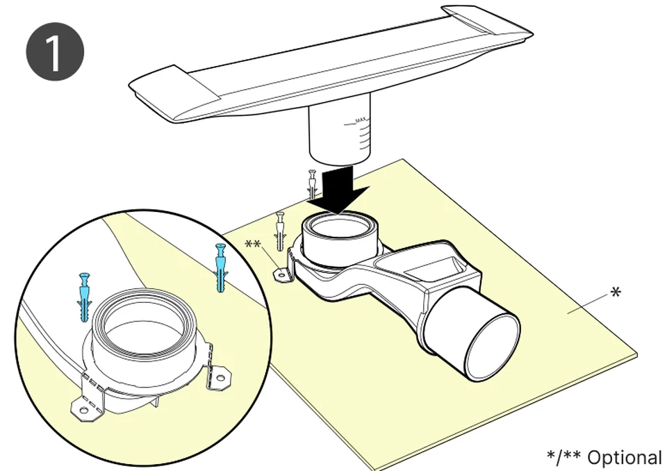
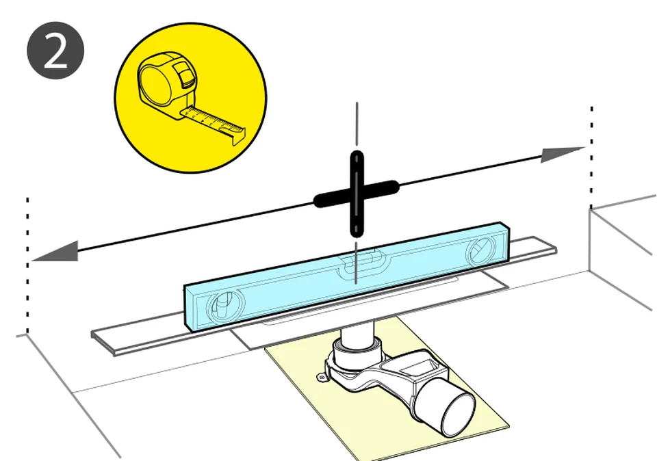
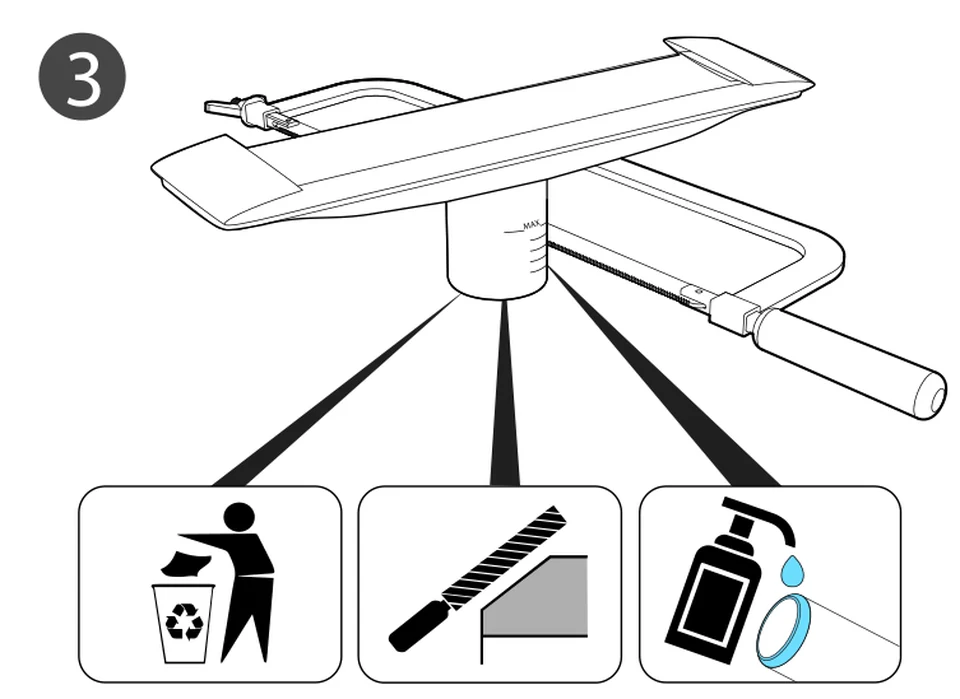
Installation step by step.
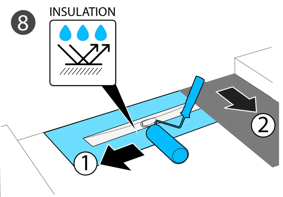
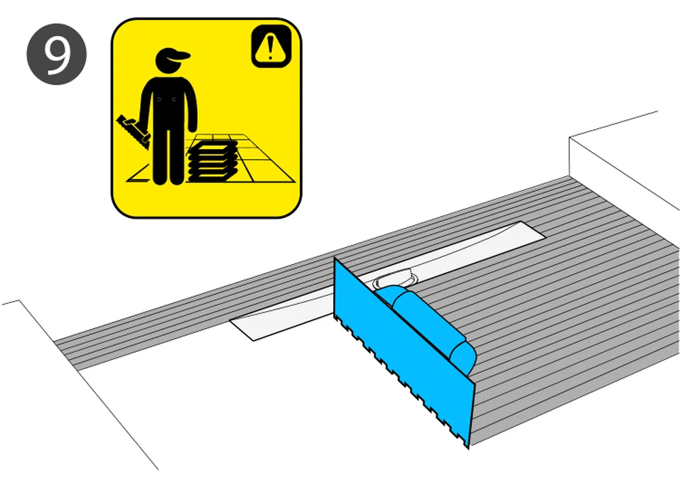
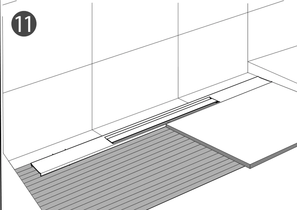
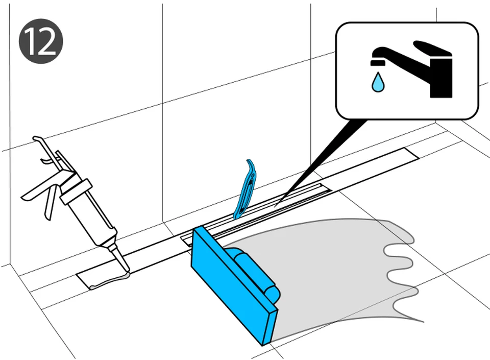
Twelve steps from the pipe connection to the finished joint. Click a step or let it run.
Frequently asked questions.
Which lengths is the Pera shower channel available in?
60, 80, 100, 120, 140 and 160 cm. The channel can be cut on site down to 32 cm.
Which build height does Pera need?
60 to 100 mm, measured from the top of the sealing collar.
How much water does Pera drain?
0.80 l/s, that is 48 l/min, with the standard siphon. The trap water height is 25 mm.
Can the pipe direction be set on site?
Yes. The drain pot rotates through 360 degrees and has a DN 50 outlet with an integrated trap.
Is Pera suitable for bonded waterproofing?
Yes. The waterproofing membrane is fitted at the factory and connects to the abP-tested bonded waterproofing system. Pera is tested to EN 1253 and holds a German abP.
Where is Pera typically used?
In floor-level showers in housing, hotels, spas and sports facilities, both in new build and in renovation.
Specification text for tenders.
Ready to paste into your bill of quantities (German, as used in German tenders).
Duschrinne Fabrikat Gruen, Typ Pera, oder gleichwertig, mit offenem Rinnenkörper und integriertem Gefälle, Rinnenkörper und Abdeckung aus Edelstahl 1.4301 (V2A), Oberfläche gebürstet, mit herausnehmbarem Haarsieb, 360° drehbarem Ablauftopf und Geruchsverschluss (Sperrwasserhöhe 25 mm), seitlicher Abgang DN 50, Aufbauhöhe 60–100 mm. Dichtmanschette werkseitig angebracht, für Verbundabdichtung geeignet. Ablaufleistung 0,80 l/s nach EN 1253, abP-geprüft. Länge ____ cm (60 / 80 / 100 / 120 / 140 / 160), vor Ort kürzbar bis 32 cm. Oberfläche ______ (E1 Edelstahl / E9 Anthrazit / E7 Bronze / E4 Gold). Art.-Nr. LP13-H24L___E_.
Copy text